Each I/O connector on your desktop PC’s entrance panel, defined
I’m a giant proponent of DIY PC constructing and I have a tendency to explain it as “comparatively simple.” For probably the most half, the whole lot simply plugs in the place it ought to. However there’s one side of placing collectively a brand new laptop that even I don’t get pleasure from: the entrance panel I/O connectors.
The entrance panel is a weird array of USB headers, audio connectors, and push-button pins which might be so fiddly and complex, and infrequently the cables solely appear to simply attain the motherboard spots the place they should go, so plugging them in generally is a problem. Plus, the connectors it’s worthwhile to plug in can range relying in your PC case.
Not like RAM and graphics playing cards, entrance panel I/O connections aren’t so simple. Right here’s a fast breakdown of the totally different I/O connectors you’re more likely to see and what all of them imply.
Energy swap
A very powerful connector it’s worthwhile to plug in appropriately is the ability swap. That is the one which connects the bodily energy button in your PC to the motherboard and permits it to inform your system to begin. With out it, you possibly can’t bodily boot your PC (until you’re prepared to brief the connectors, however that’s exterior the scope of this text).
Jon Martindale / Foundry
The ability swap is normally a small black plastic header, with two feminine ports for the motherboard’s pins to fit into. It’s typically accompanied by different entrance I/O connectors which may be clumped collectively, since all of them plug into the identical space in your motherboard.
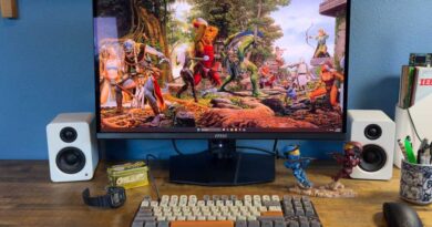
However no matter your specific case’s orientation, the ability swap at all times plugs in the identical approach. The I/O pins are normally—however not at all times—positioned on the bottom-right of the motherboard. Discuss with your guide or producer’s web site when you’re not sure. (There must also be labeling subsequent to the pins to point out you which of them to attach the place.)
Jon Martindale / Foundry
When connecting headers like the ability swap to the motherboard’s entrance panel I/O pins, ensure you’re plugging it in the precise approach. There’s a optimistic (+) and damaging (-) aspect to it. In the event you plug it within the incorrect approach, nothing unhealthy will occur—it simply received’t work.
Jon Martindale / Foundry
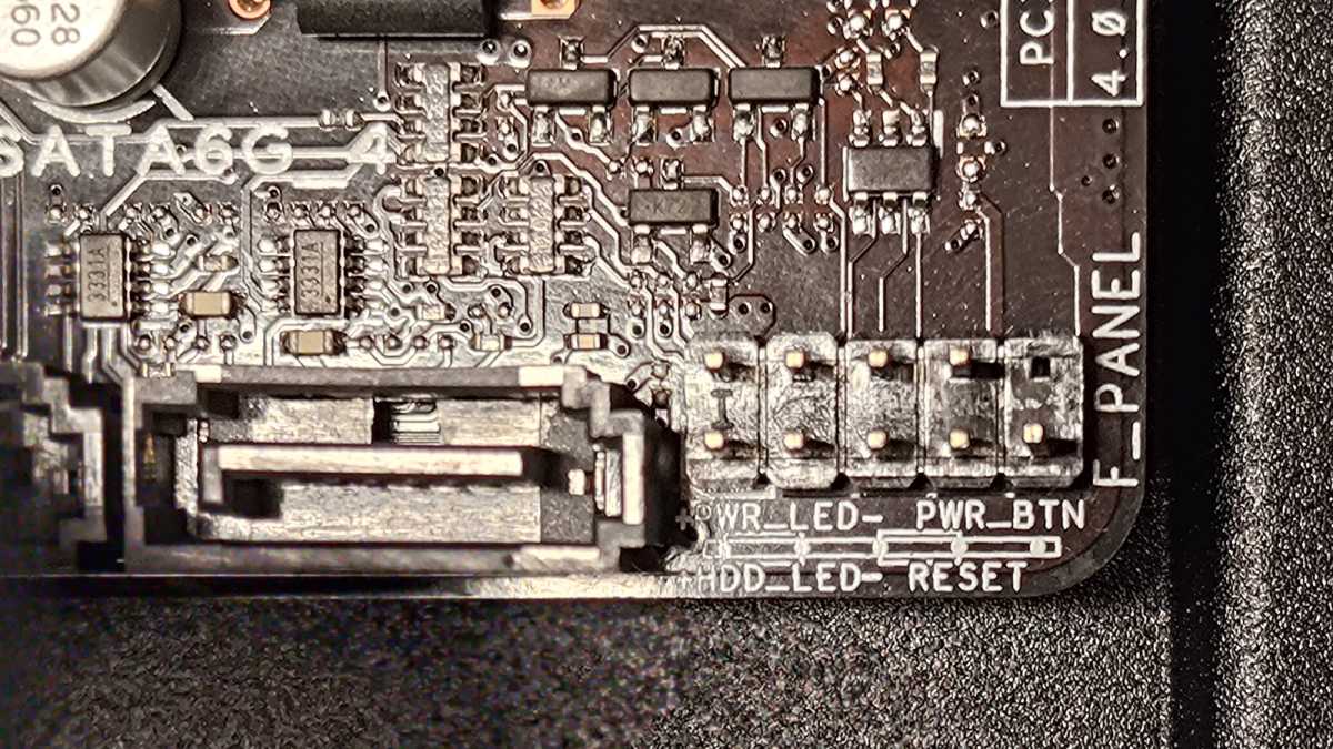
To seek out the proper orientation, take a look at the again aspect of the ability swap header and also you’ll see a small triangle indicating the optimistic aspect.
Reset Change
Like the ability swap, the reset swap is usually a unified positive-and-negative header with each pins collectively. Use the reverse-side arrow to determine which is which for proper orientation, after which plug it into the motherboard’s entrance panel I/O pins per standard.
Energy LED
In the event you like your PC to have a flickering LED when powered on as a visible indicator, you’ll want to verify it’s related, too. The ability LED might be helpful for troubleshooting, or simply letting your PC’s state at a look (stable is on, flashing is asleep, and off is off). Alternatively, when you hate LED indicators, you should use LED stickers to dam them!
Like the ability swap, the ability LED headers plug into the identical I/O pins on the motherboard—however not like the ability swap, the LED headers will come as separate optimistic and damaging headers. As soon as plugged in, the LED ought to mild up the following time you energy your system on.
Storage LED
Some desktop instances have a secondary pair of LED headers for storage. Though normally labeled as “HDD” for laborious drives, it really works simply the identical for contemporary SSDs. When plugged in, the LED will flash at any time when the storage drive is being accessed.
In case your case has it and you discover it helpful, plug it in the identical approach you’ll the ability LED. Find the optimistic and damaging pins on the motherboard and fix the proper headers to every. Nothing unhealthy will occur when you get it incorrect, apart from it not working. Simply swap if that occurs.
USB 2.0
Jon Martindale / Foundry
Although much less frequent now in trendy PC instances since we’ve principally moved on to quicker requirements, you may nonetheless see USB 2.0 headers, particularly in older instances and a few legacy-supporting chassis.
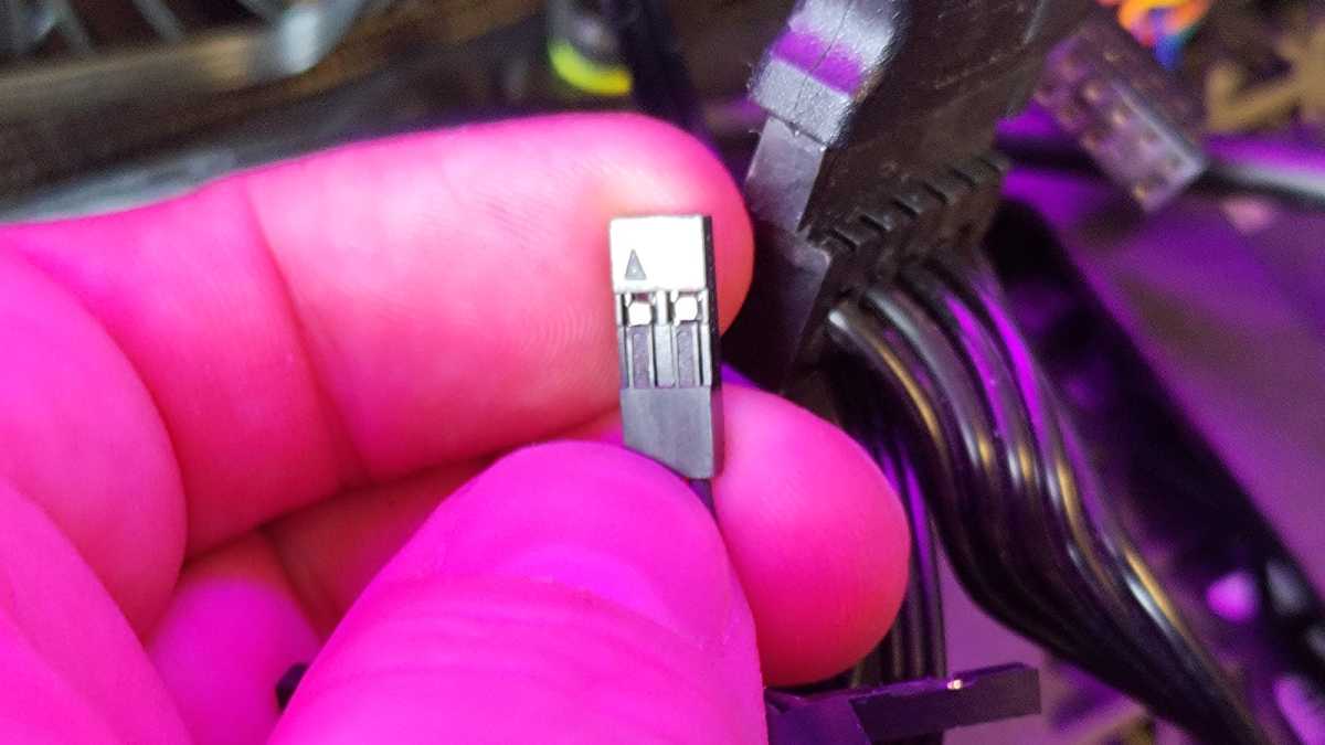
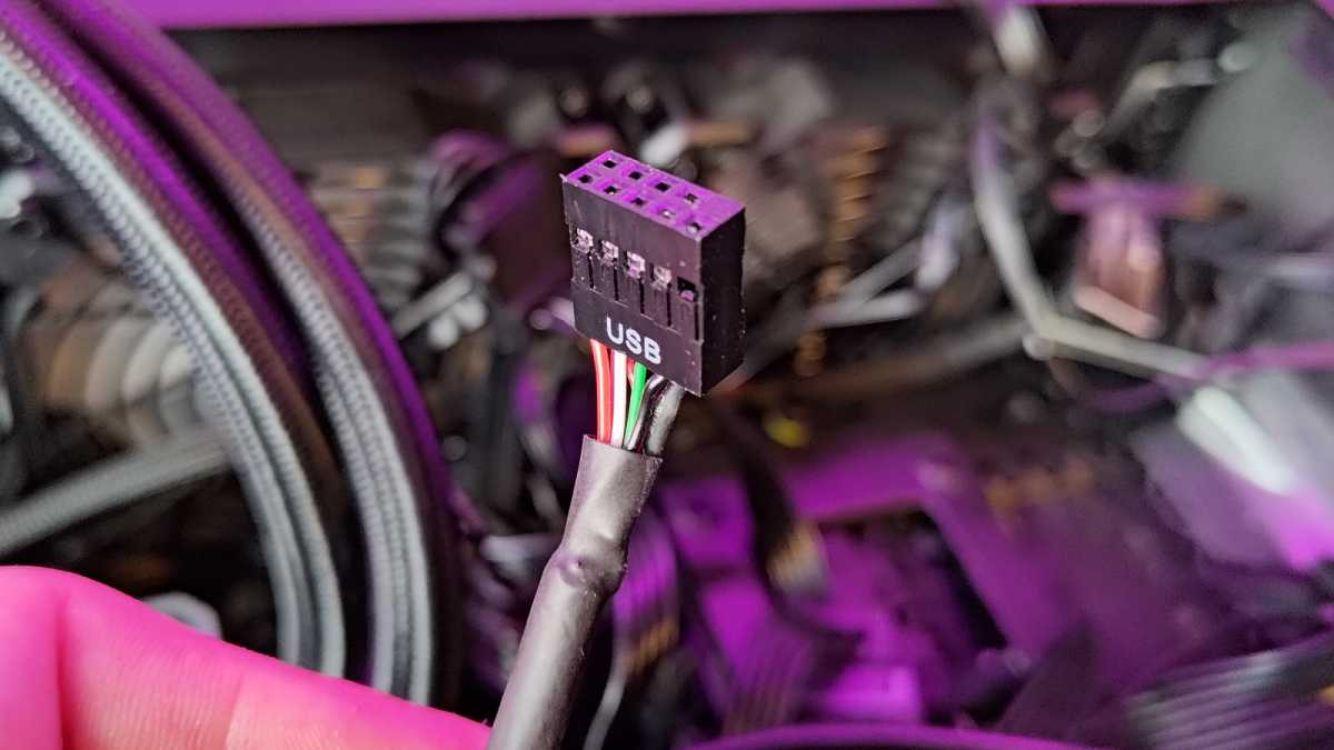
The USB 2.0 header could have a USB label in addition to one in every of two configurations: a singular 9-pin structure with one nook blocked off, or a flatter 5-pin structure. They’re each “the identical,” with the 9-pin structure being two USB 2.0 headers in a single, successfully powering two USB ports with a single header. (The fifth pin within the USB 2.0 header is particular, and it will get shared by each USBs within the 9-pin structure.)
The distinctive 9-pin structure of USB 2.0 is a clue to the place it plugs in in your motherboard, as there aren’t many headers that even match this pin structure. In the event you want further steering, discuss with the labeling on the motherboard or test your motherboard’s guide.
USB 3.0
Jon Martindale / Foundry
USB 3.0 is quicker than the older USB 2.0 customary, however even these are beginning to fall by the wayside. Nevertheless, you may nonetheless run into these, particularly in additional budget-oriented setups.
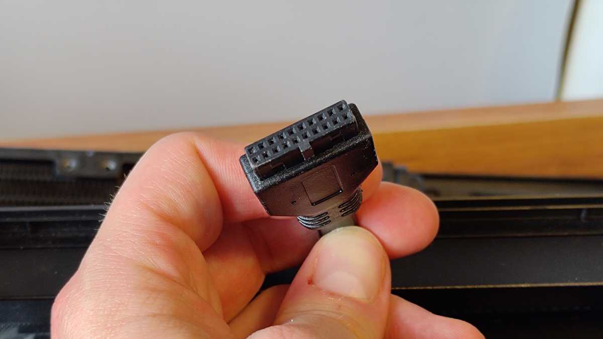
The USB 3.0 cable is bigger and thicker, with a 20-pin connector that will or could not have the twentieth pin blocked out. In different phrases, you’ll both see two rows of 10 holes OR a row of 9 and a row of 10. (The lacking gap in a single row is for alignment/orientation functions.)
USB 3.1 and USB 3.2
Jon Martindale / Foundry
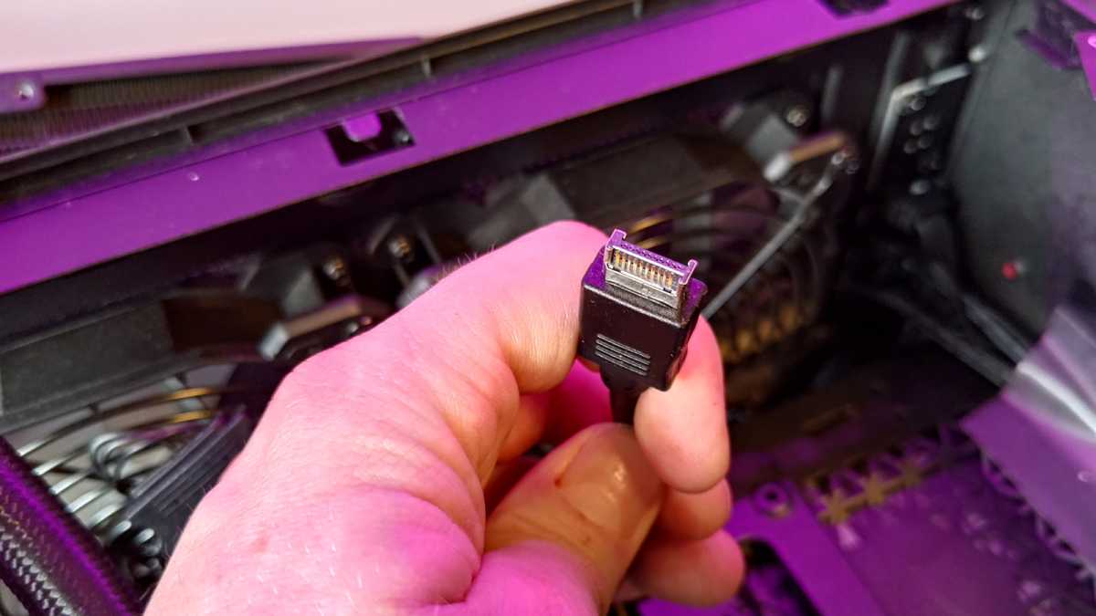
Beginning with USB 3.1, the entrance panel connector was revamped to be smaller and extra compact whereas supporting a boosted 24 pins. It’s typically used along side entrance panel USB-C ports.
The header has a little bit of an “H” form with bare pins on both sides, and it plugs right into a socket with an aluminum encompass (which will help it stand out a little bit from the remainder of a motherboard’s connectors).
Jon Martindale / Foundry
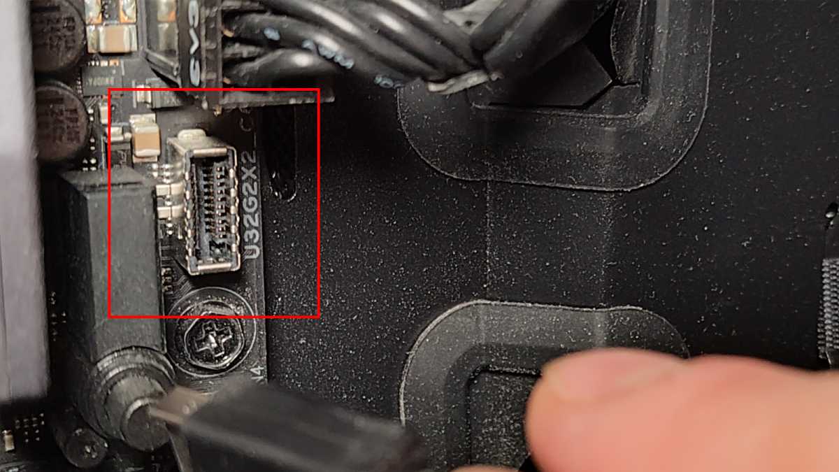
When you’ve got hassle discovering the place to attach it in your motherboard, search for labeling alongside the strains of “USB3.1,” “USB31C,” “U32G1,” and even “UB32GX2,” which is what I see by myself motherboard.
Audio
Jon Martindale / Foundry
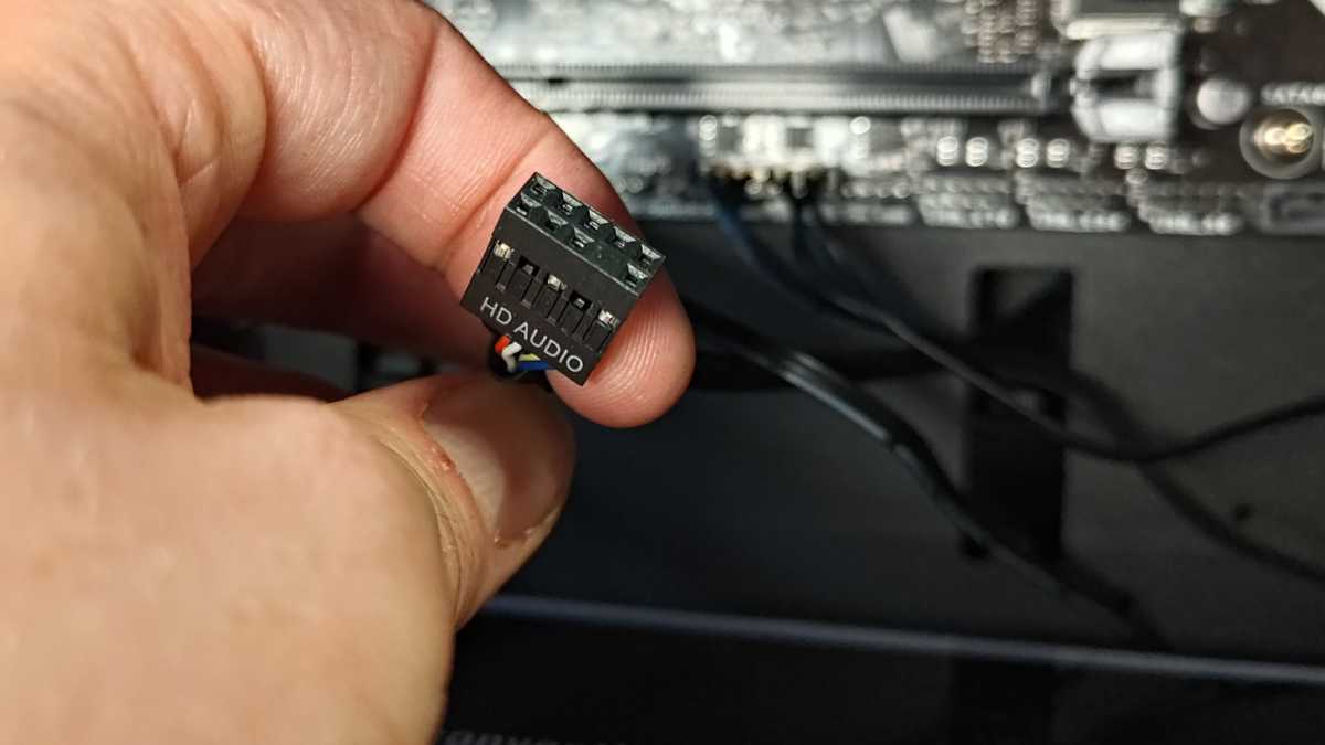
Whether or not you’ve gotten a mixed 3.5mm jack for each headphone and microphone, or separate ports for every of them, they output to a single header inside your PC case. The audio header seems similar to the USB 2.0 header, so don’t get them confused! Thankfully, there’s normally an “Audio” label on it—or comparable—that can assist you out.
This one normally plugs into the underside of the motherboard alongside all of the USB 2.0 headers and diverse I/O pins.
Speaker
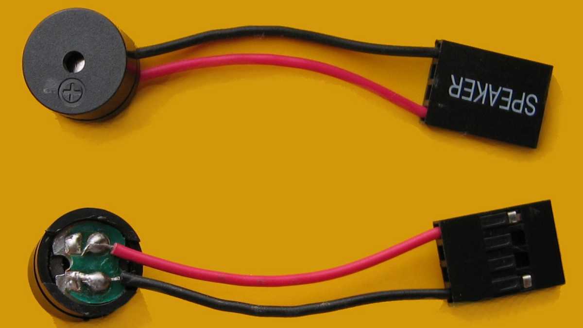
Hans Haase / Wikimedia
Much less frequent nowadays however nonetheless helpful is the motherboard speaker, a small system that attaches to the identical I/O headers as the ability swap and LEDs. It’s the little beeper that makes a noise at any time when your PC first begins to submit after you’ve hit the ability button. It’s additionally what can beep at you if there’s an issue along with your PC and it’s worthwhile to troubleshoot it. These beep codes might be invaluable.
In case your motherboard has an LED readout, or another type of visible error codes, you then don’t really want the speaker. However if you’d like one, it sometimes plugs into the I/O headers simply the identical. Use the rear arrow to search out the proper orientation and discover the pins on the motherboard.